Translate this page:
Surface inspection and gloss measurement
24 November 2021
| When designing spray systems, it is important to ensure that the sensor technology is matched to the size of the spray cone and the spray volume of the application in question. Furthermore, the geometry of the spray cone and the spray quantity depend on the medium used (primer, adhesive, solvent, water, alcohol, paint, etc.) as well as on the spray nozzle opening, the overpressure and the spray quantity dosage. Particularly when using tough, adhesive media (glue) as a spraying agent, it can happen that part of the spray nozzle opening sticks, which leads to a change in both the spray quantity and the spray geometry. As a result, the spray jet can be changed in terms of direction as well as opening angle. When designing a spray jet control system, it is important to address some key questions. ► Press release (Word/pdf) |
 A-LAS-CON1 L-LAS-TB-...-AL-SC Series SI-JET Series SPECTRO-1-CONLAS SPECTRO-1-FIO Series SPECTRO-1-FIO-JC |
15 April 2021
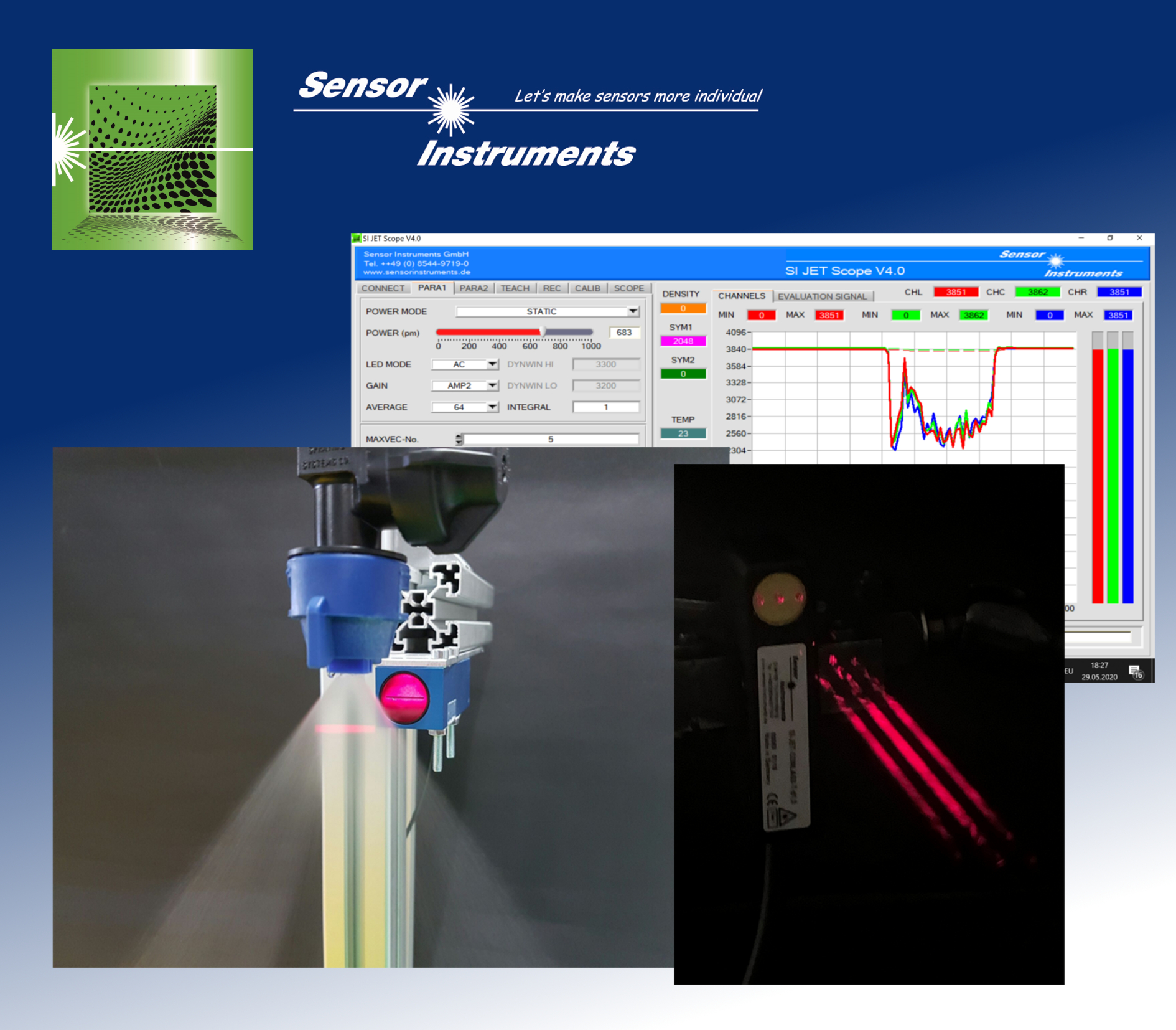
| Surface coatings are often applied by spraying. Ideally, objects should be coated homogeneously. Air pockets in the spraying medium, partial covering of the nozzle outlet apertures or an abrupt pressure fall in the spraying system can result in inhomogeneities in the spray cover and thus uneven coating of the workpiece. Timely recognition of deviation from the ideal spraying procedure can be performed via continual spray jet control. The spray jet control systems of the SI-JET series and the SPECTRO series from Sensor Instruments GmbH provide information about the spraying quantity, the length of interruptions and the spray jet symmetry. Three-jet systems (SI-JET-CONLAS3 and SI-JET3) two-jet systems (SPECTRO-2) one-jet systems (SPECTRO-1) and continuous light barriers (L-LAS-TB-…-SC) are available to perform the respective task. ► Press release (Word/pdf) |
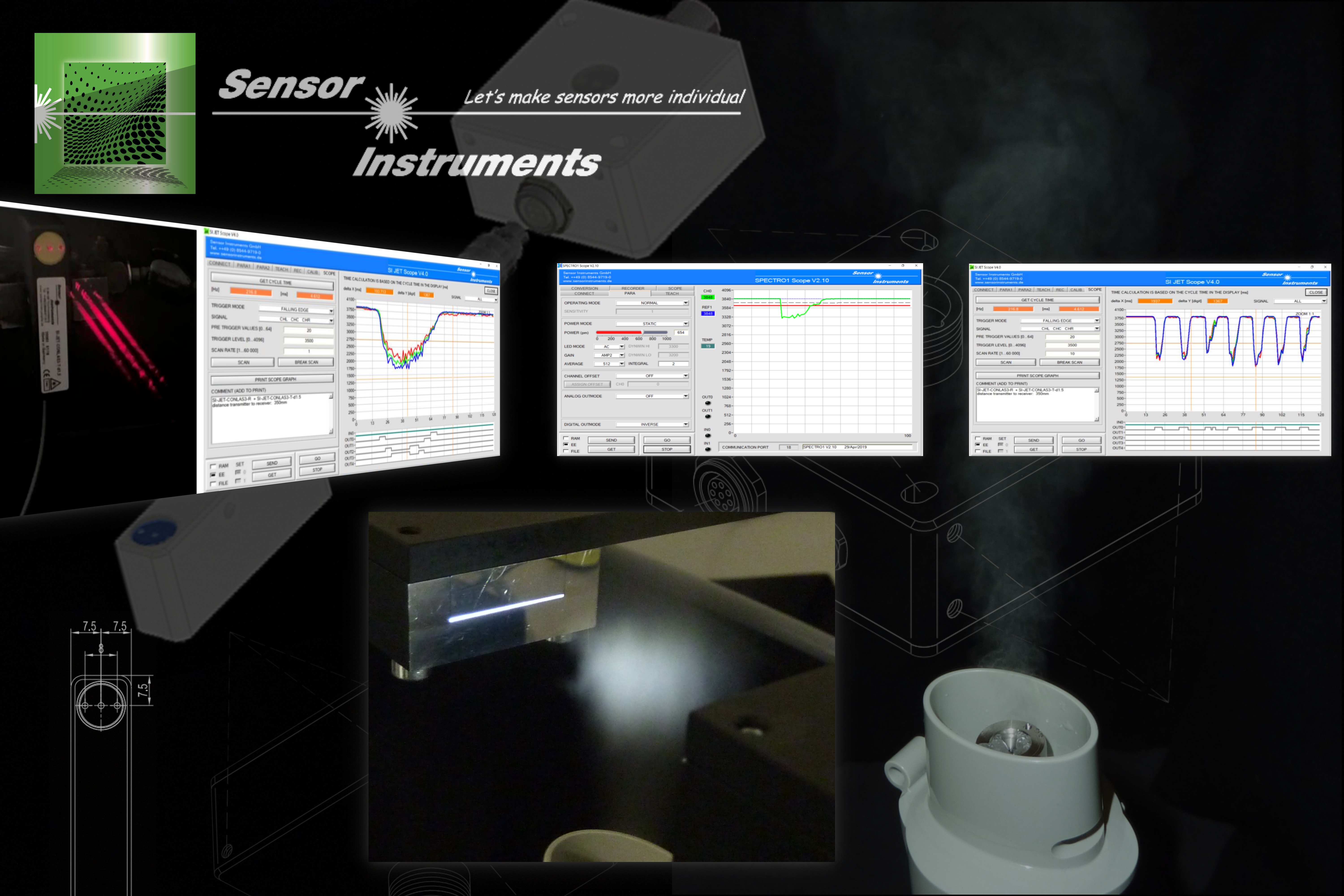 SI-JET Series SPECTRO-2 Series SPECTRO-1 Series L-LAS-TB-AL-SC Series |
15 April 2021
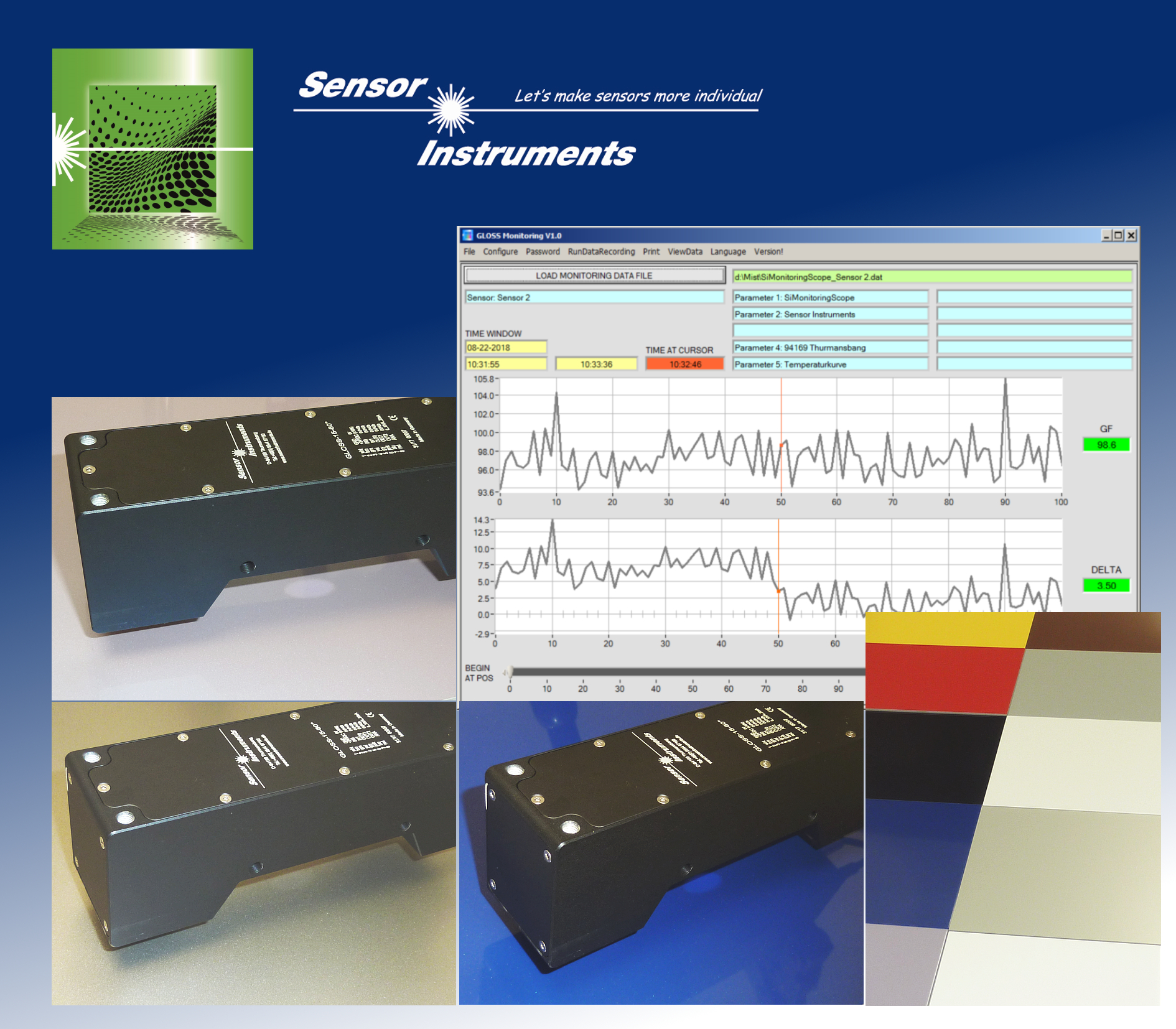
| The human eye reacts principally to differences in contrast (differences in gloss) and color. For example, if we look at freshly-installed floor boards, we immediately notice even the smallest differences in color and gloss between the individual panels. It comes therefore as no surprise that manufacturers do their very best to minimize difference in color and gloss between the individual panels. The checking process conducted to this end was previously performed using hand-held offline measuring units; Sensor Instruments GmbH has developed an inline alternative. Our GLOSS series gloss detection sensors can measure the gloss grade of painted wooden panels in the angles 20°, 60° and 85° at a distance of 20mm, 15mm and 5mm to the surface (depending on the sensor type: GLOSS-20-20°, GLOSS-15-60°, GLOSS-5-85°). ► Press release (Word/pdf) |
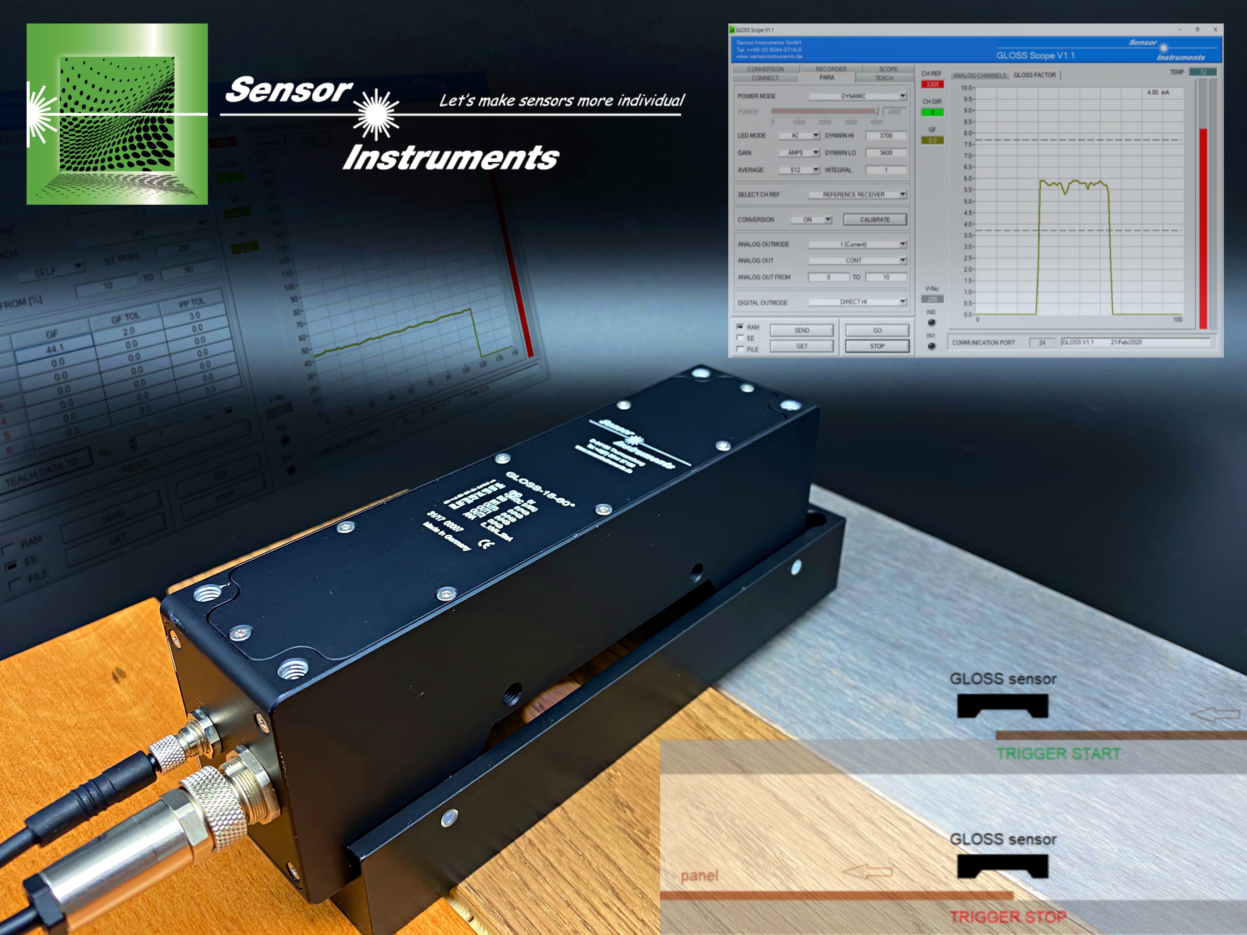 GLOSS-20-20°, GLOSS-15-60°, GLOSS-5-85° GLOSS Series |
21 January 2021 SPECTRO-M-10-MIR/(MIR1+MIR2) - Press release #4
| The use of oils is imperative in the forming process of metals. For example, the application of cutting oils to metal bands ensures low wear on the punching tools. Drilling oils make an essential contribution to the protection of the drilling and milling tools during chipping processes. Oils also serve to protect semi-products such as sheets and metal foils against corrosion. After further processing, it is important to remove the oil residues from the finished products as completely as possible. This task is performed by special cleaning systems, in which the metal parts are washed and blown dry. In order to ensure that environmental specifications are maintained during the application of the oils, and to ensure that the process is economical, it is advisable to ascertain the quantity of the oil applied. Oil quantity measurement can be performed INLINE. A number of measurement procedures are available to this end and which constitute the focus here. The cleaning process can be monitored using the same sensors. The challenge is to determine even small quantities of oil residue accurately, preferably INLINE. Electrically conducting components such as copper busbars or power current lines require the lowest possible transfer resistance. A residual oil layer would pose a problem as this restricts the conductive efficiency to a considerable degree. ► Press release (Word/pdf) |
SPECTRO-M-10-MIR/(MIR1+MIR2) SPECTRO-M Series |
22 December 2020 SPECTRO-M-10-MIR/(MIR1+MIR2) - Press release #3
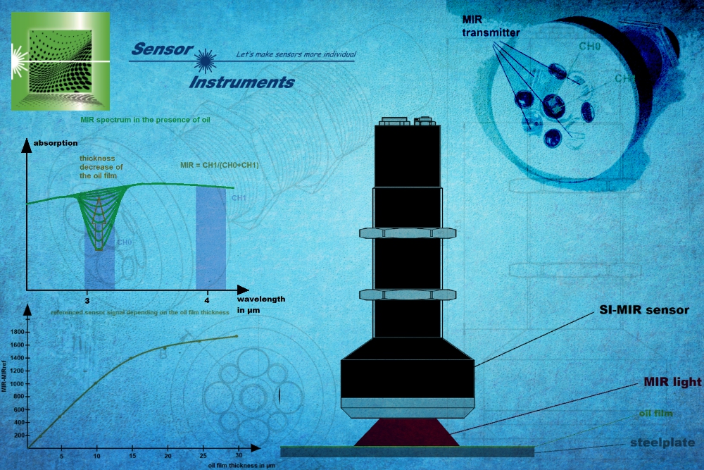
| Producers of blanked and flexible parts are increasingly using evaporated punching and drawing oils. Such processes need an outcome which minimizes the oil residue on the punched or formed metal parts in order to obviate the need to subject the products to a cleaning process. The question is: how much of the oil remains on the component and how long does the evaporation process take? Our SPECTRO-M series answers this question! To this end, we applied five drops of oil (5x20µl) to a degreased steel plate and spread it over a 70mm diameter surface. The oil layer thickness at the start of the measuring procedure amounted to some 25µm. The SPECTRO-M-10-MIR/(MIR1+MIR2) sensor was then placed on the center of the oil and the measurement started: The MIR sensor was used to view two measuring windows, both of which were located in the mid-wavelength infrared light range (MIR range). One of these two wavelength range windows reacts to the presence of oil (here referred to as CH0), whilst the second measuring window (CH1) gave no reaction. This change in the two measuring windows upon the presence of oil can be used to ascertain the amount of oil within the detection range. ► Press release (Word/pdf) |
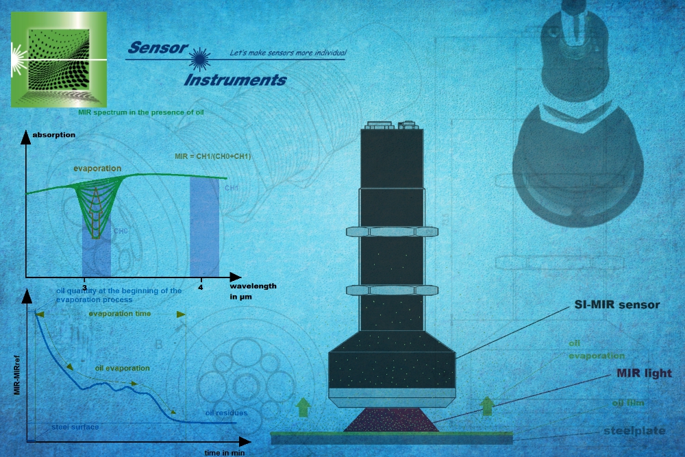 SPECTRO-M-10-MIR/(MIR1+MIR2) SPECTRO-M Series |
14 December 2020 SPECTRO-M-10-MIR/(MIR1+MIR2) - Press release #2
| Those wishing to measure the layer thickness e.g. of a homogeneous layer of printing ink on paper can adopt the grammage method as an adequate approach. The grammage of a printing ink is not all that different from that of paper with a thickness of between 0.05 mm and 0.2 mm. The use of accurate scales should be able to produce a reliable result. What happens when we replace printing ink with oil and paper with a 1 mm steel sheet? We would probably come to the limits of the grammage method. We still need a reliable method of determining the thicknesses of oil layers without too much effort. One possible solution is the fluorescence method, using UVA light to stimulate fluorescence. Secondary emissions are emitted in the visible wavelength range. The intensity of the fluorescence establishes the measure for the thickness of the respective oil layer. We should take into consideration however, that the signal strength (fluorescence) is not only dependent on the layer thickness but also the nature of the oil used and the metal surface which functions as a reflector and exerts an influence on the signal level. There are also a number of oils with only a minimal or no fluorescence effect and which cannot be measured to establish the layer thickness. Taking the mid-wavelength infrared light range (MIR) into consideration, we see that the oils previously investigated all exhibit a significant absorption in a certain wavelength range, whilst other wavelength ranges do not respond to the presence of oil. Were we to exclude this oil-sensitive wavelength window from the MIR spectrum and then compare its absorption behavior in standardized fashion with the absorption observed in a second, oil-neural wavelength window, we have a first approximation of a proportional relationship between the thickness of the oil layer and the standardized signal. The SPECTRO-M-10-MIR/(MIR1+MIR2) sensor if fitted with exactly this wavelength window. ► Press release (Word/pdf) |
 SPECTRO-M-10-MIR/(MIR1+MIR2) SPECTRO-M Series |
2 December 2020 SPECTRO-M-10-MIR/(MIR1+MIR2) - Press release #1
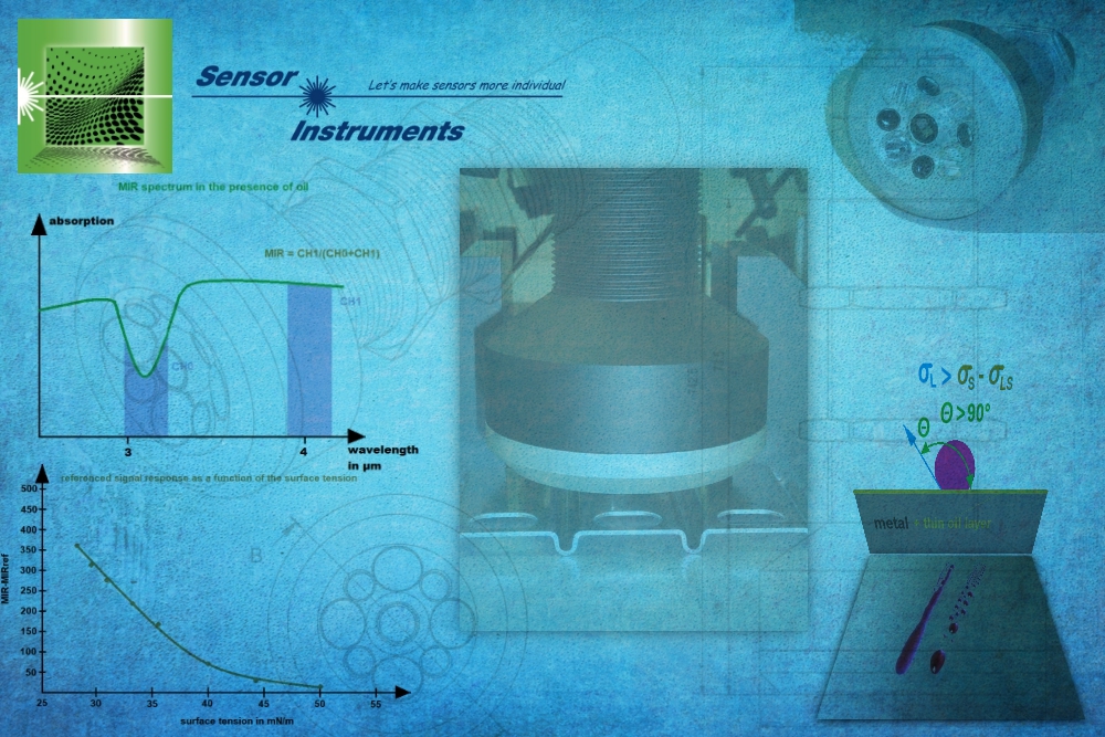
| The tension is rising! The users of cleaning units for metal parts – e.g. stamped parts – wait with baited breath to see what the washing sequence brings forth. Has the surface tension exceeded the threshold of 38 mN/m or has it even climbed to 44 mN/m? A metal component is generally taken to have been de-greased if one of these values (which of the two, depends on the intended application) has been exceeded. Previously, test ink was used to demonstrate the surface tension. These liquids are available in various surface tension values, usually starting with 30mN/m to 50mN/m in steps of 2mN/m (30mN/m, 32mN/m, …, 48mN/m, 50mN/m). If the test ink does not roll off the metal surface after application, the surface tension of the metal part lies above the value specified for the test ink. On the other hand, if the test ink does roll off the metal surface, the surface tension of the metal lies below the value specified for the test ink. In this way, the surface tension can be ascertained with an accuracy of 2mN/m. What does the surface tension mean in relation to the property of the respective metal surface? De-greased metal surfaces present a surface tension above 50mN/m (ascertained with the test ink method). On the other hand, if a metal surface is covered with an oil film, (for example, through oiling the punching strip before punching), the value of the surface tension can fall under 30mN/m, depending on the thickness of the film. The test ink method is therefore capable of determining whether the metal surface is covered with an oil film, or whether it has been removed (de-greased). Even oil films of less than 1µm can be demonstrated with this method. Experiments with various oils have shown that almost all oils have a selective absorption rate in the mid-wavelength infrared light range (MIR). Using this characteristic means that the comparison of two MIR wavelength ranges (one range is the neutral range, i.e. the wavelength range in which no noticeable absorption occurs as a result of the oil) can be used to determine the thickness of the oil layer after calibration of the SPECTRO-M-10-MIR/(MIR1+MIR2) measurement system, and in a subsequent step, to display the respective surface tension value. ► Press release (Word/pdf) |
 SPECTRO-M-10-MIR/(MIR1+MIR2) SPECTRO-M Series |
31 July 2020
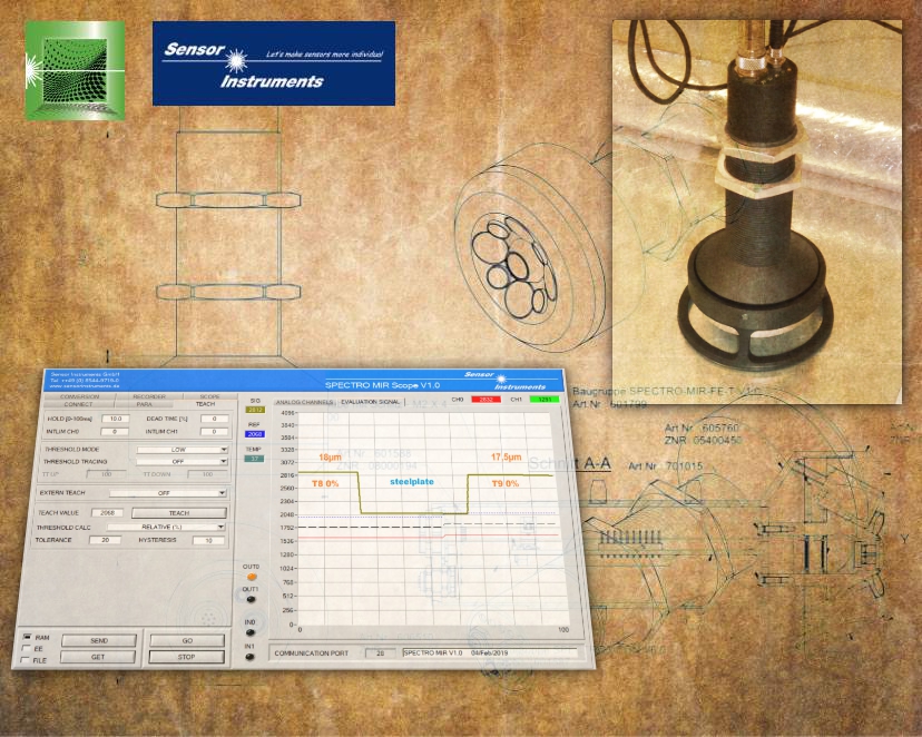
Measuring the thickness of thin and transparent plastic films It is important to be able to measure the thickness of stretch films after production, including after the stretching procedure. The SPECTRO-MIR-10 measurement system enables fast and precise inline and offline measurement and is not affected by extraneous light. The Windows®-Software SPECTRO MIR Scope V1.0 can be used to calibrate the measurement system to the respective film type. In addition to the parametrization software, the monitoring software SPECTRO MIR Monitoring V1.0 is available, which is used to save measurement data and display it graphically and numerically, including trends. ► Press release (Word/pdf) |
 SPECTRO-MIR-10 SPECTRO-MIR Series |
30 June 2020
Dear manufacturers of vinyl flooring, don't worry, we will find the gap! From the range of RED series edge detectors the RED-50-L and RED-110-L sensors are especially suited for detecting gaps, i.e. in this application the distance of two parquet panels. These edge detectors reliably detect gaps starting from a depth and width of approx. 0.05mm. With the supplied software the laser edge detector can be adapted to different surfaces: From dark to bright, and from matt to glossy. With a maximum scan frequency of typ. 85kHz the sensor also is excellently suited for high-speed object handling. ► Press release (Word/pdf) |
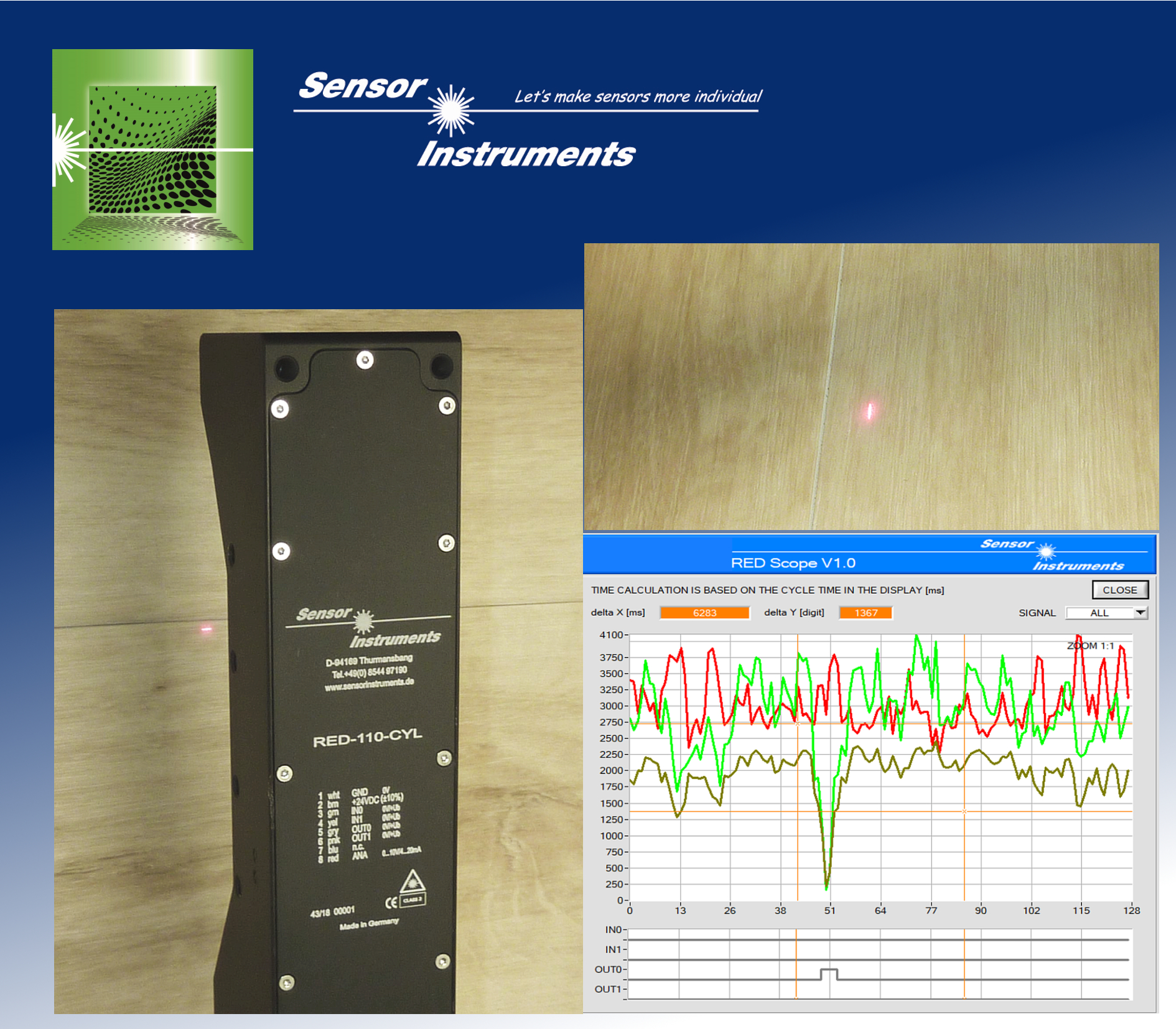 RED-110-L RED Series |
22 June 2020
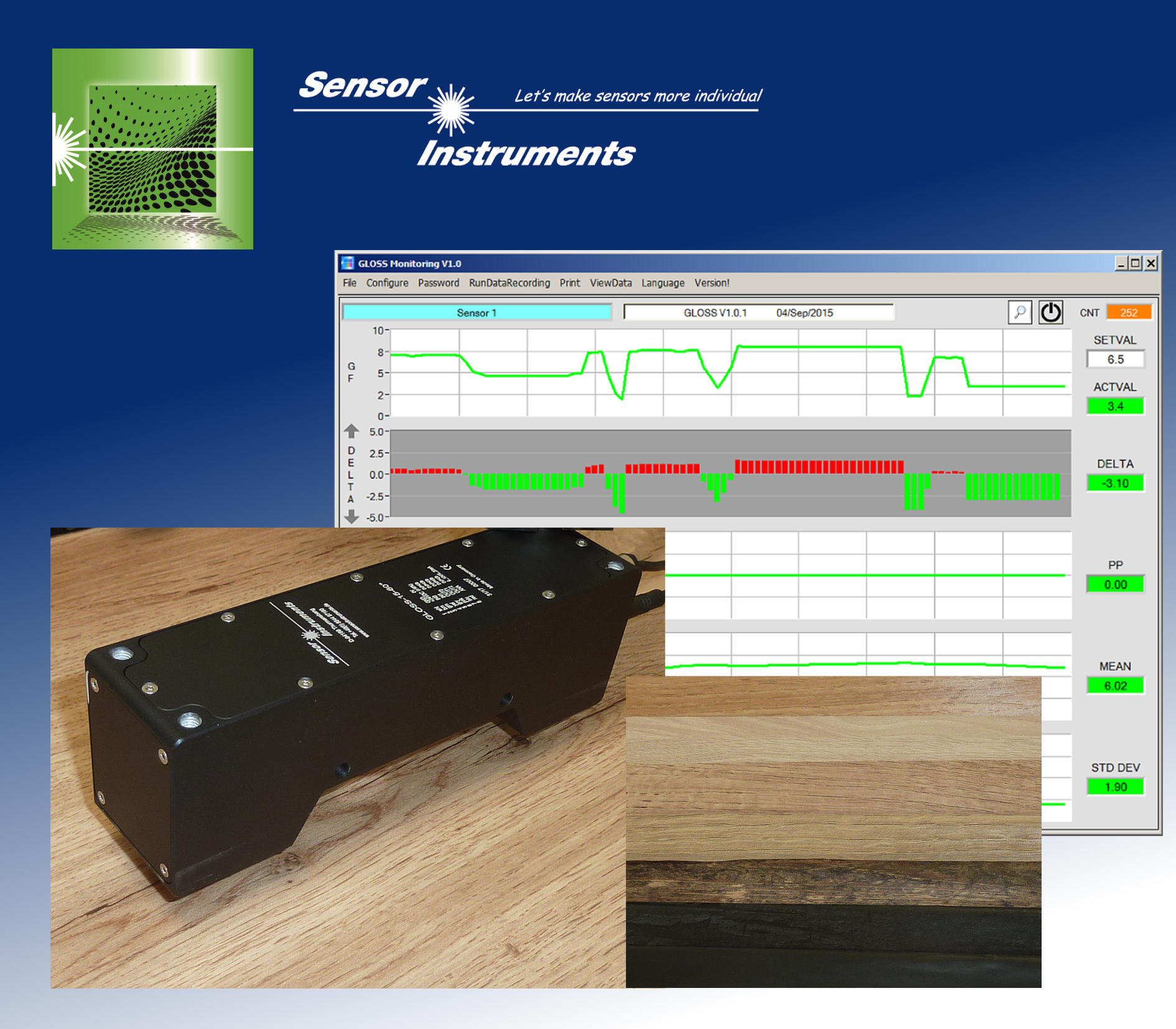
When metal plates are painted, both their color and their gloss factor must be measured after the painting process. Gloss measurement is performed inline and immediately after the painting process to allow a quick response to possible deviations of the gloss factor from the respective setpoint value. A gloss sensor of the GLOSS series (GLOSS-15-60°) that measures the gloss factor at a distance of 15mm from the object is used for this application. ► Press release (Word/pdf) |
 GLOSS-15-60° GLOSS Series |
26 May 2020
Apart from plastic foils, paper-based foils are more and more used both in the furniture industry and in the flooring sector. Nowadays decor papers for example are available for kitchens, furniture elements, and laminate flooring. However, one requirement applies both to plastic and paper-based decor foils: Constant quality and brilliant appearance must be ensured during production. The inline gloss sensor GLOSS-15-60° that continuously measures the gloss factor of decor foils definitely makes a decisive contribution to achieving this. ► Press release (Word/pdf) |
 GLOSS-15-60° GLOSS Series |
14 May 2020
In the production of radial and axial fans the checking of the correct frequency response depending on the applied DC voltage is one of the final steps. The easiest method for measuring the frequency is to use a transmitted-light sensor (for example a D-LAS2-d1.0-T + D-LAS2-Q-d1.0-R-HS, featuring a switching frequency of typ. 300kHz). In many cases, however, the fan blades of the respective fan version only can be accessed from one side for testing, so that a reflected-light sensor must be used as an alternative. The edge detectors of the RED series (RED-50-L or RED-110-L) are excellently suited for such applications. ► Press release (Word/pdf) |
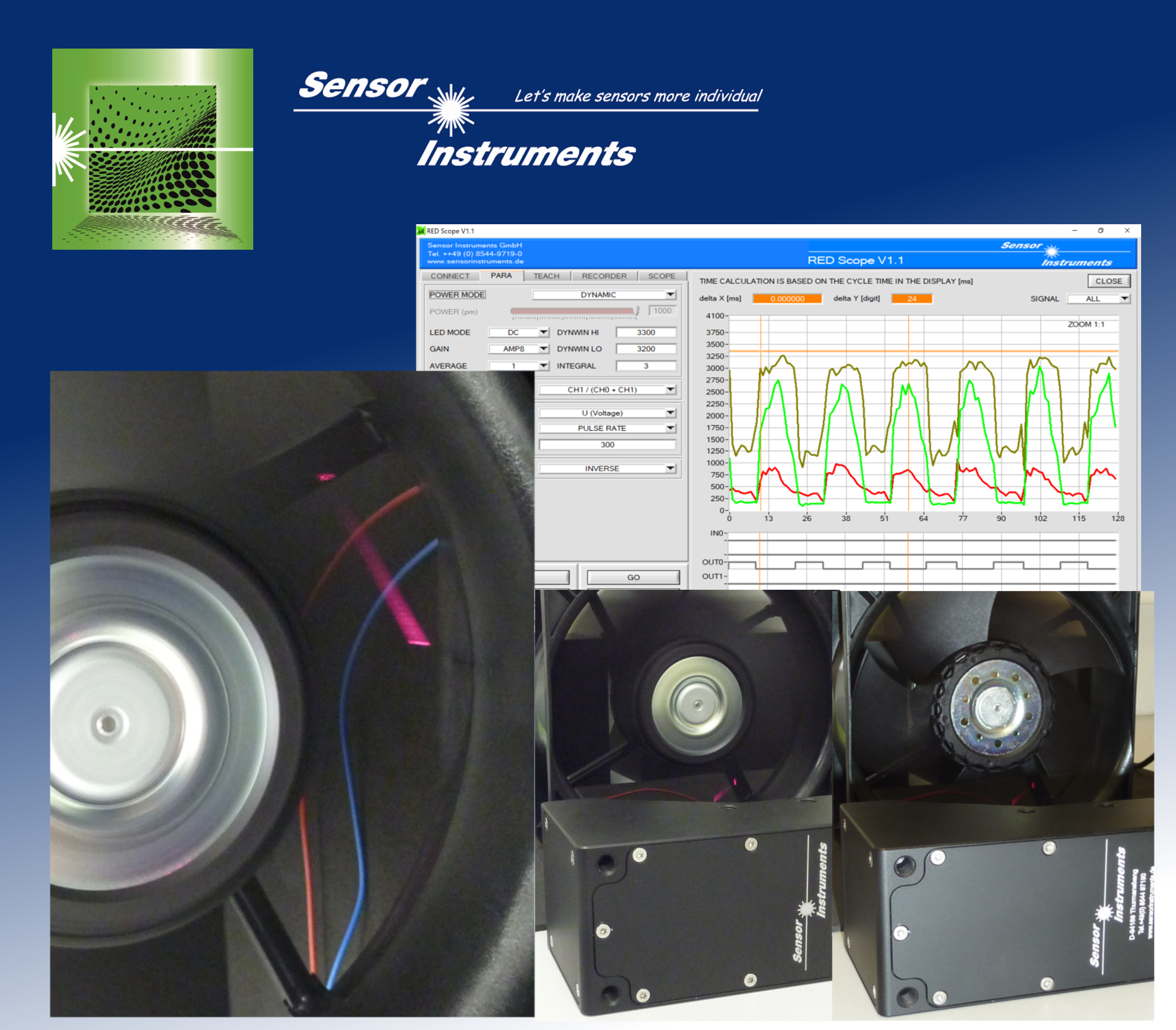 RED-50-L, RED-110-L RED Serie |
7 April 2020
In the production of aluminium flex-pipes the decisive factor is not really the measured length of the flex-pipes but rather the number of existing folds, because due to the material's "accordion effect" the actual length cannot be accurately measured. In this application an edge detector of the RED series (e.g. RED-50-L or RED-110-L) is used to count the folds. During edge counting the aluminium flex-pipe is moved along the laser sensor. The sensor provides a digital output signal for every edge. ► Press release (Word/pdf) |
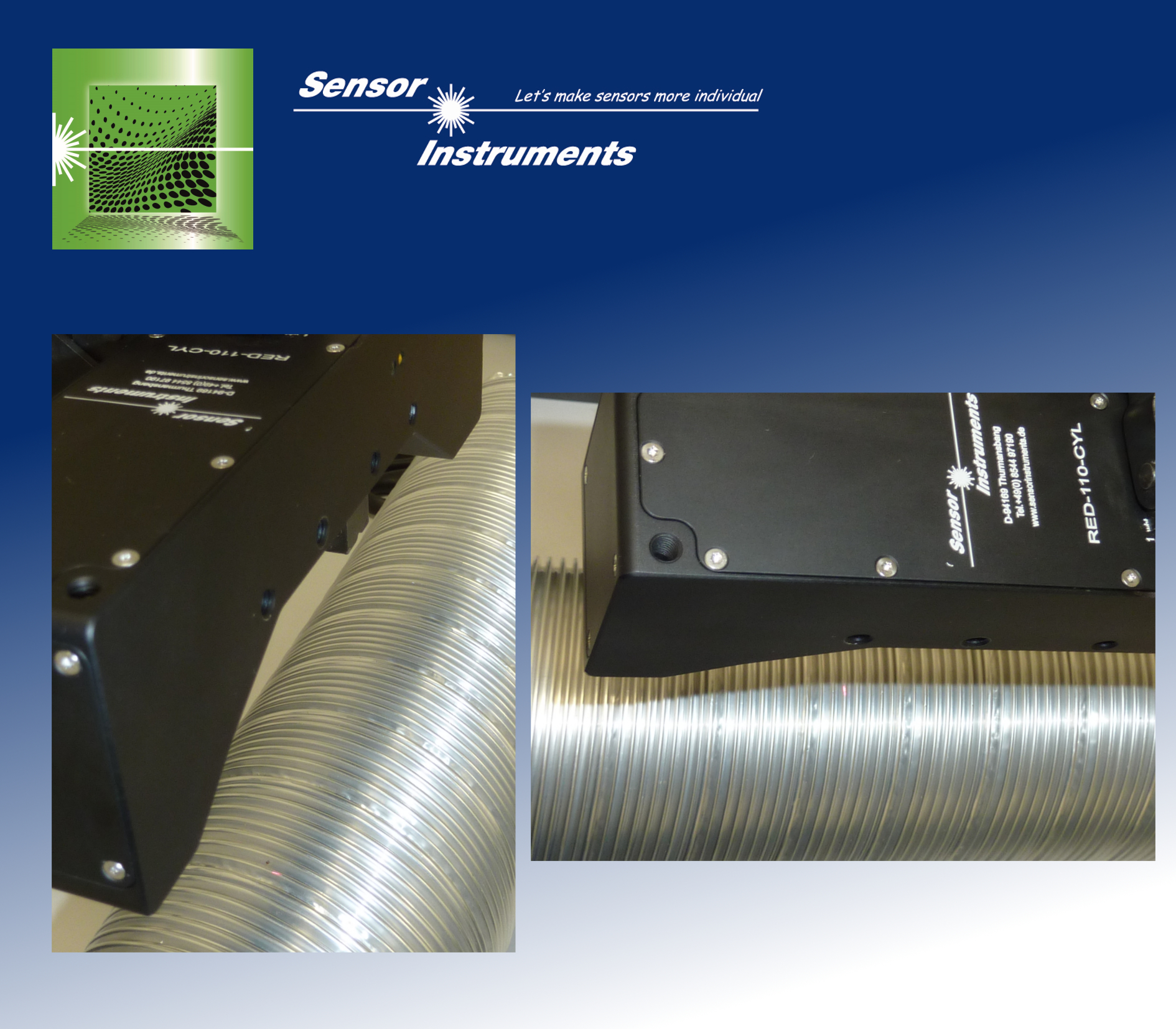 RED-50-L, RED-110-L RED Series |
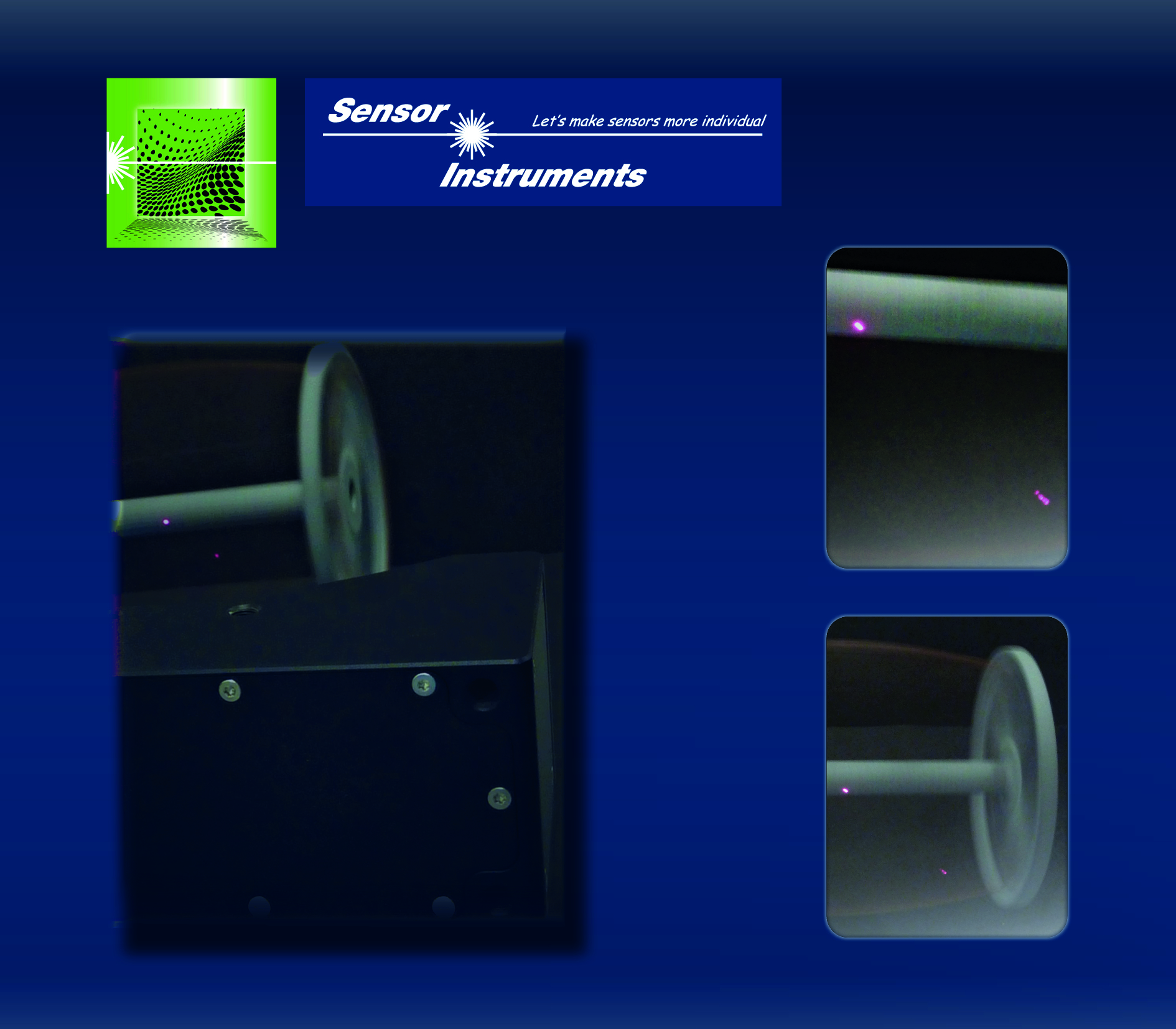
23 March 2020
The task is to measure the frequency of compressor wheels that are used in turbochargers. These wheels may reach speeds of up to 300,000 revolutions per minute. Usually these compressor wheels have about 10 blades and are made of milled aluminum. If the frequency of these compressor wheels should be determined optically it must be taken into consideration that every blade causes a signal change - which means that up to 3,000,000 switching processes must be expected per minute, resulting in a frequency of approx. 50 kHz (of the blades). Even an edge detector of type RED-50-P or RED-110-P with its maximum scan frequency of typ. 100 kHz will work up quite a "sweat" here. ► Press release (Word/pdf) |
.jpg) RED-50-P, RED-110-P RED Series |
9 March 2020
In the production of sandpaper it must be ensured that the grain size of the abrasive material (e.g. aluminum oxide or silicon carbide) always lies within the permitted tolerance range. Previously performed laboratory tests showed that the gloss factor of the sandpaper surface correlates quite well with the grain size: The smaller the grain size, the higher the corresponding gloss factor. ► Press release (Word/pdf) |
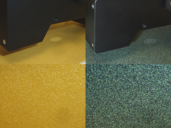 GLOSS-5-85°, GLOSS-15-60° GLOSS Series |
27 February 2020
In the production of cables or of high-voltage lines the individual insulated conductors or aluminium wires must be stranded, which in practice is performed by stranding machines. In this process the individual conductors or wires are wound around a core wire. The core wire with relative ease can be inspected for possible wire breaks by using a suitable laser light barrier operating with the transmitted-light method. An inspection of the outer conductors or outer wires can be realised with a correspondingly adapted edge detector of the RED series (RED-110-P-F60). ► Press release (Word/pdf) |
 RED-110-P-F60 RED Series |
4 February 2020
Some aspects of technology very well can be compared to real life: The direction is not always up or down. After a "down" there often is an "up" again, and this also applies to edges: As a rule a rising edge is followed by a falling edge, and vice versa. In the series of edge detectors the RED-60-CLS-L and the RED-60-CLS-P now allow the detection of rising and falling edges. ► Press release (Word/pdf) |
RED-60-CLS-L, RED-60-CLS-P RED Series |
29 April 2019
Hand-held units for measuring the gloss level have been successfully used in the industry for years, and three viewing angles have been established as a standard: 20°, 60° and 85° measured from the vertical axis. The paper industry is an exception here and primarily uses viewing angles of 45° and 75°. The gloss level is determined by measuring the direct reflection at the object surface to be inspected. |
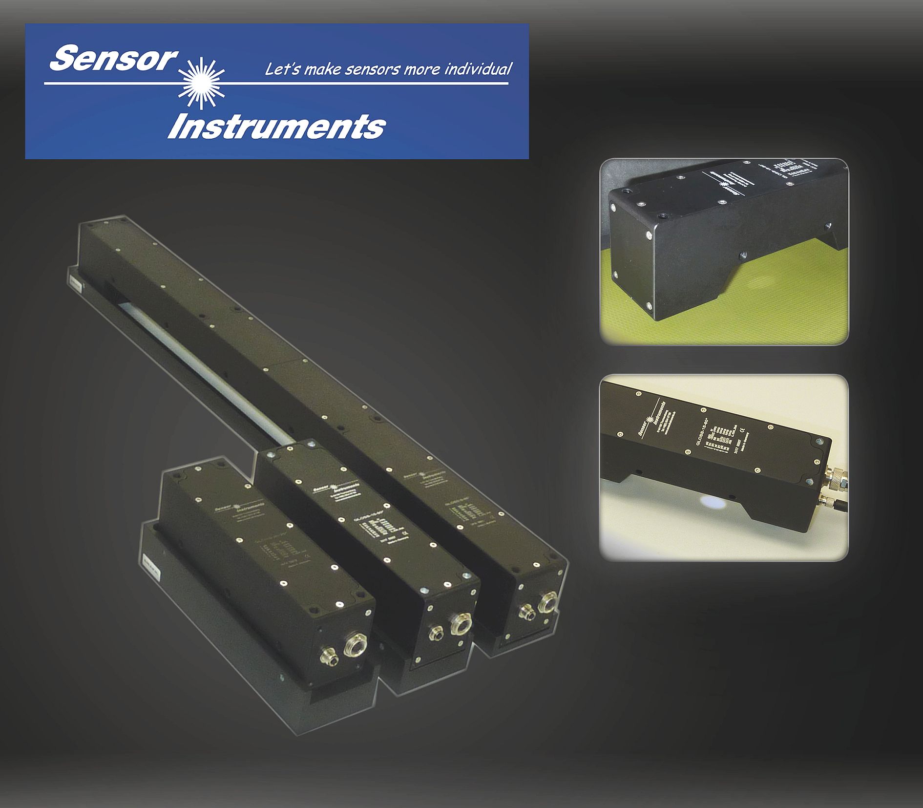 Inline gloss meters GLOSS Series |
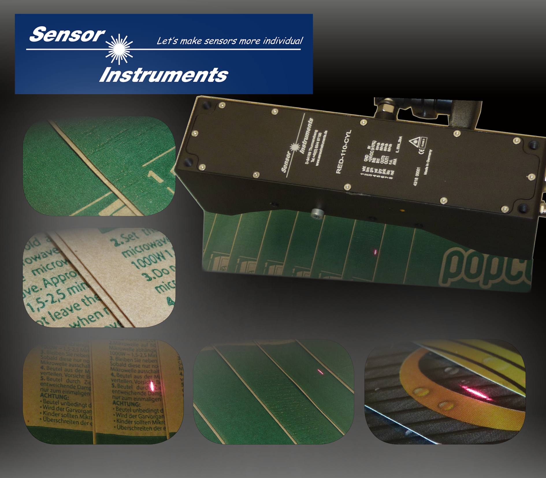
20 February 2019
In the production of oil and air filters for the automobile industry these filters must reach the required throughput rate, which is achieved by folding the filter material so that it provides a large filter surface on a minimum of space. Depending on the filter type there are differences in the fold depth and in the numbers of folds. |
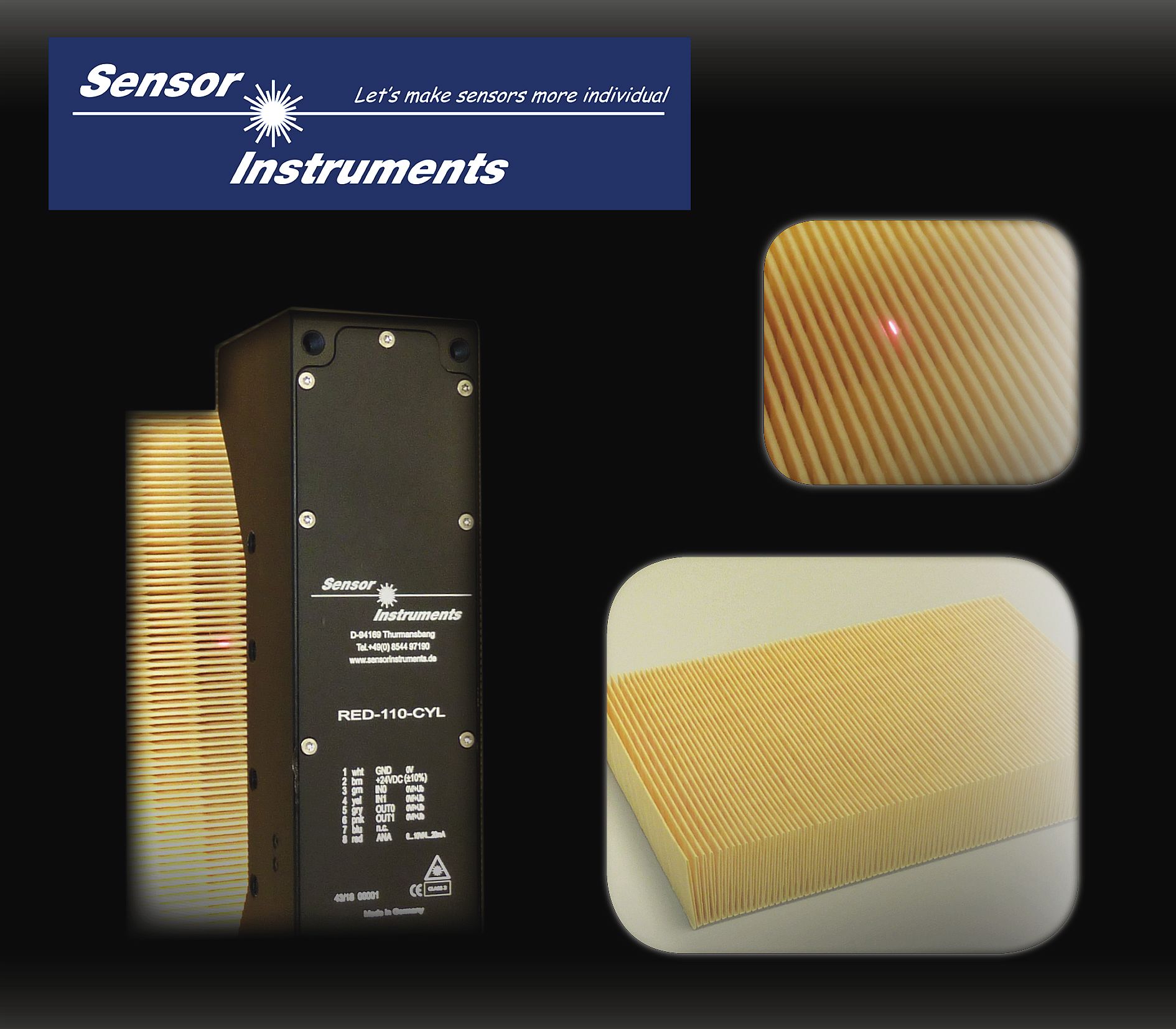 |
| Laser edge detector RED-110-L |
7 February 2019
For the detection of welding seams, contrast or color sensors would seem to be the proper solution, because in most cases the welding seam optically shows a clear difference from the surrounding product surface. In everyday practice, however, it turns out that these methods involve frequent readjustment and reparameterisation. |
 |
| Laser edge detector RED-110-L |
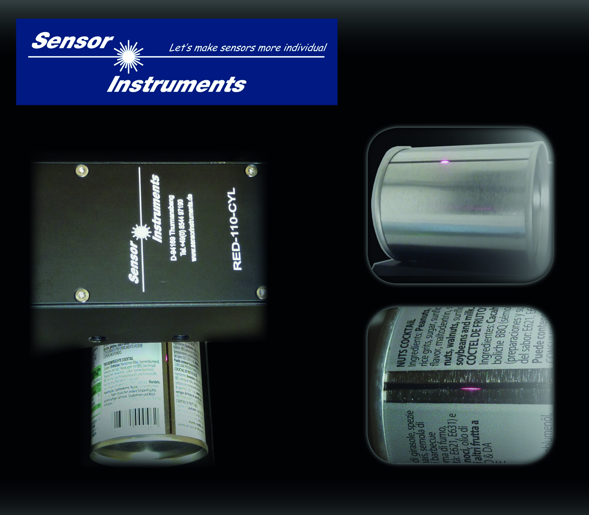
21 January 2019
Conventional detectors particularly reach their limits when they have to detect and count stacked transparent objects such as plastic drinking cups of plastic caps. Especially in the process of packaging, however, it is of great importance to place the exact number of objects in a packaging unit. Such problems now can be solved with the RED series (a RED-110-L was used for this application). |
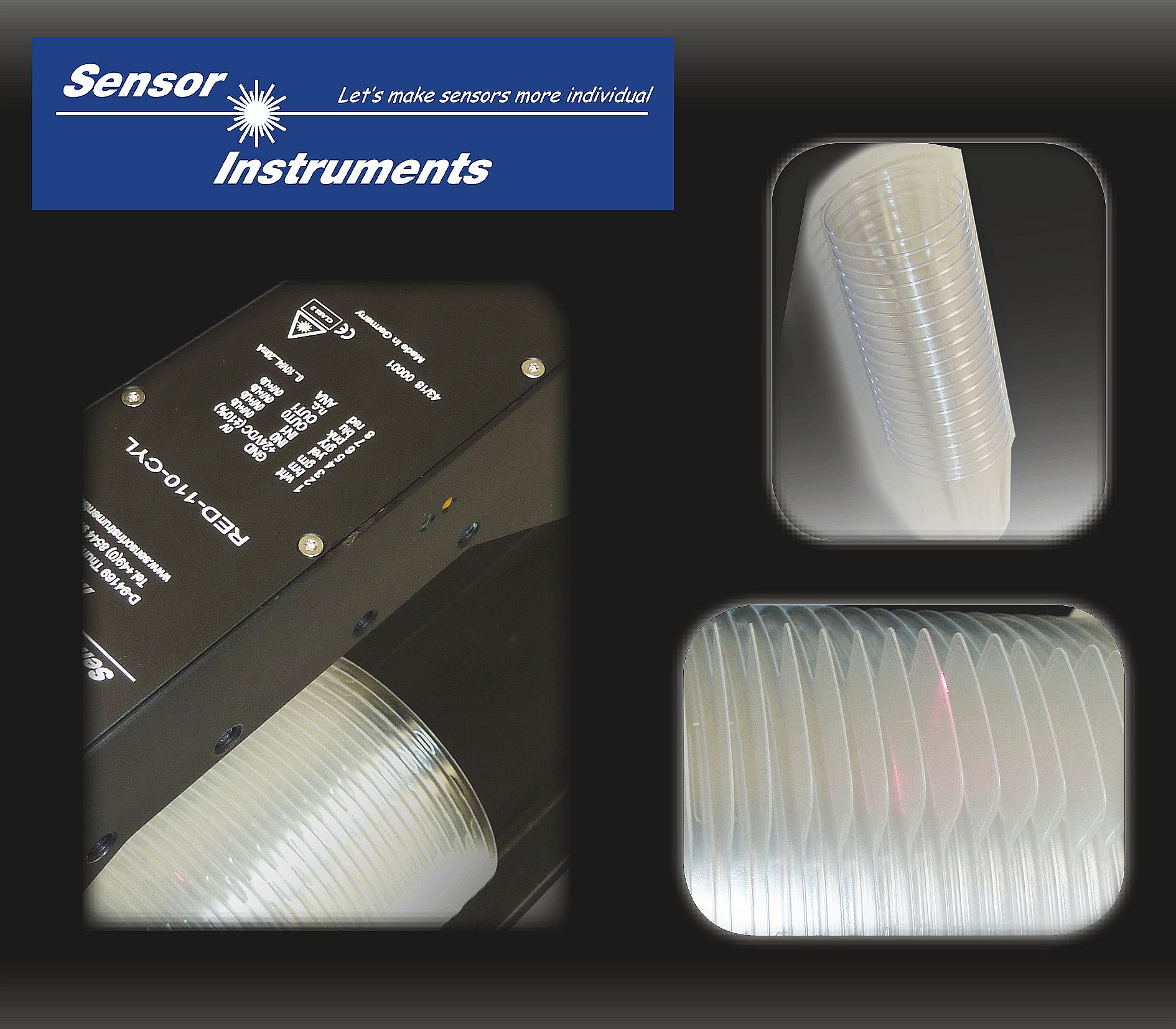 |
| Laser edge detector RED-110-L |
26 November 2018
At first everything seemed to be quite clear, just another measurement task that we surely would manage without any problems with one of our GLOSS series sensors. According to the descriptions provided by the customer it seemed to be gloss grade measuring task, and at the beginning the only question seemed to be at which angle measurement should be performed: 20°, 60° or 85° from the vertical? |
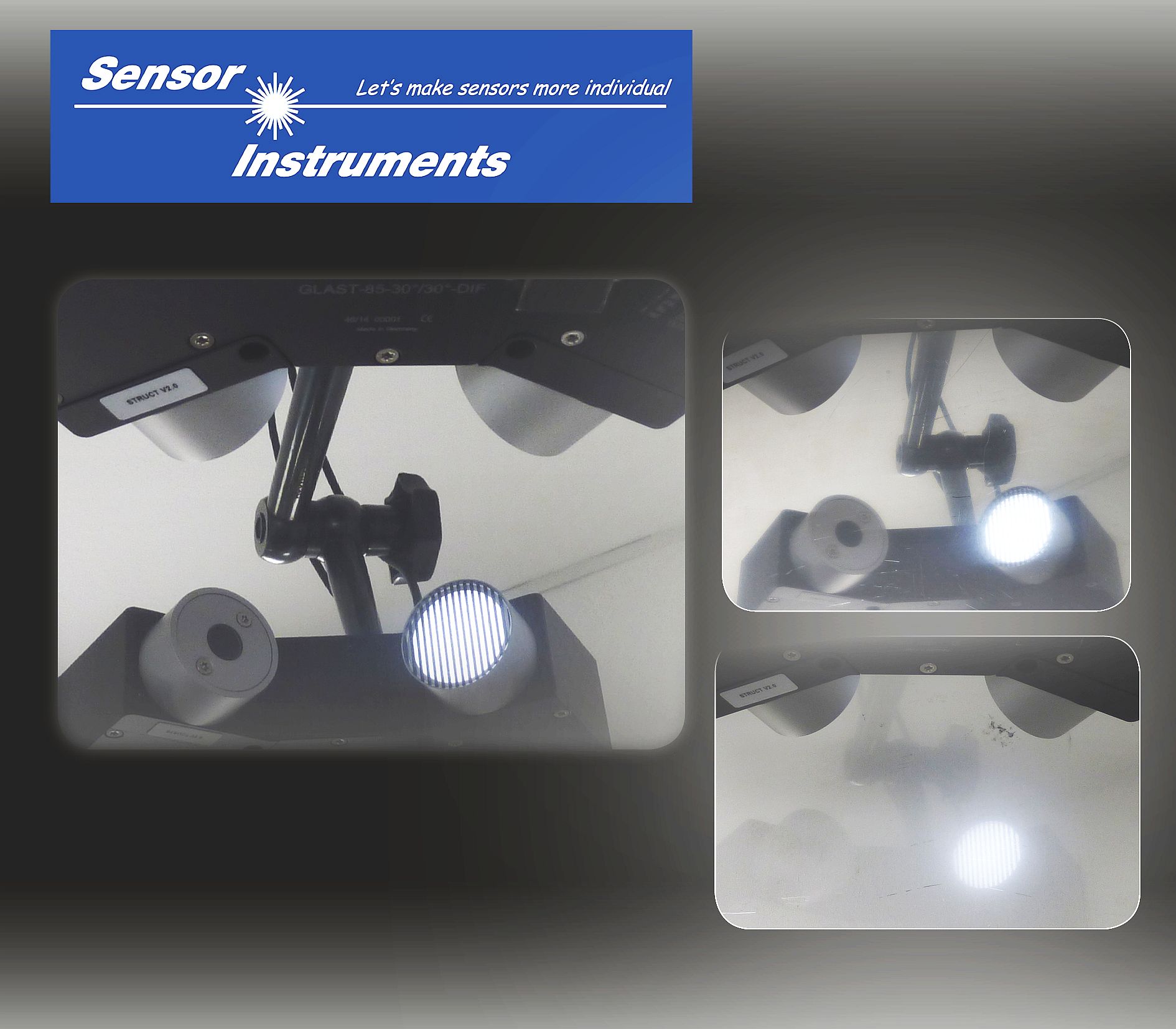 |
| Gloss sensor GLAST-85-30°/30°-DIF-1.0/1.0 |
19 November 2018
|
When cartons, magazines, or single sheets are packed, it must be ensured that each package has the correct number of items. In most cases such material is transported in shingled form before, as with magazines, newspapers or advertising prints, it is packed by means of a compensating stacker. Depending on the thickness of the individual copies and on their transport speed (up to 10m/s) the shingled stream may have differing heights in this process. ► Press release |
 |
| Laser edge detector RED-110-L |