


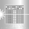
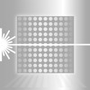
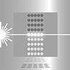


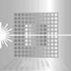
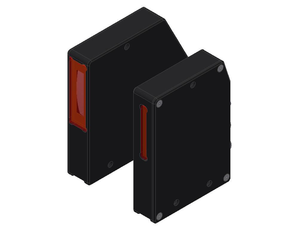
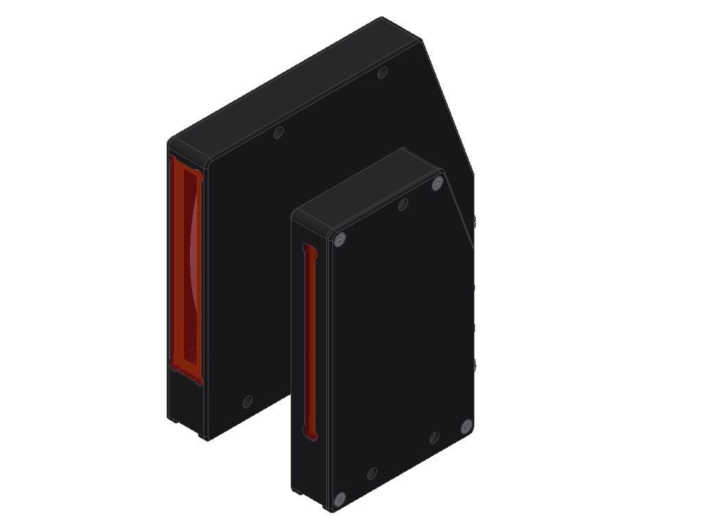
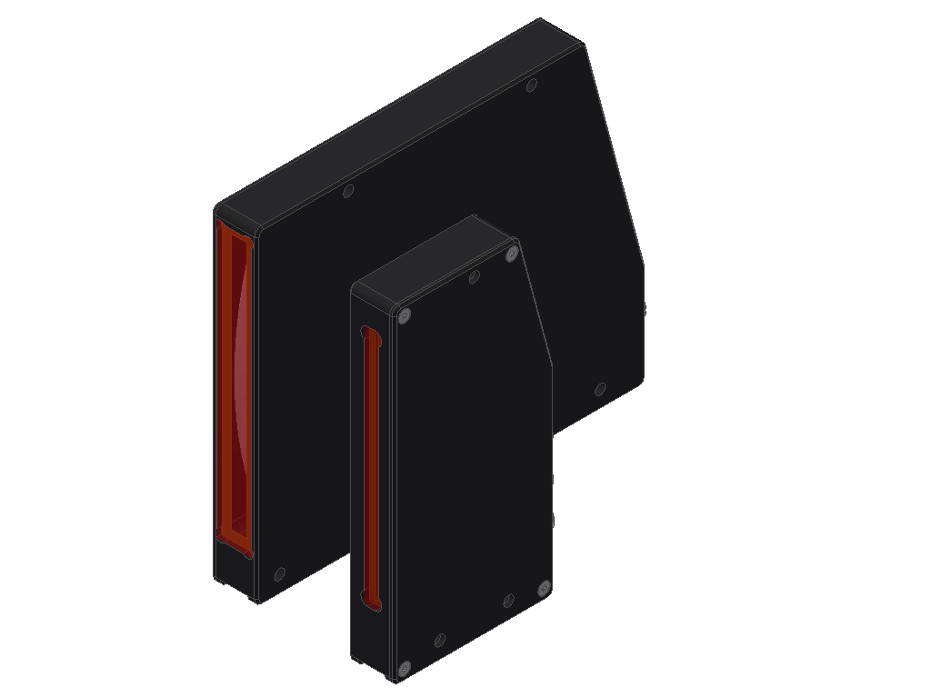
L-LAS-TB-AL-SC Series
Laser transmitted light line sensors (Advanced Line Spray Control)| Type | Light source | Working distance | Meas. range/ linea- rity | Reso- lution/ repro- duci- bility | Max. scan fre- quency | Inputs/ outputs | LxWxH (mm) | Data sheet |
CAD data |
Appl. | ||
|---|---|---|---|---|---|---|---|---|---|---|---|---|
|
L-LAS-TB-28-T-AL-SC L-LAS-TB-28-R-AL-SC |
Line laser, 670nm, 0.39mW (CL. 1) | max. 2000mm | 28mm / 0.2% FSR (full scale range) | 14µm / ±14µm | 1.4 kHz | 2xIN, 3xOUT, 1xANA: 0...10V or 4...20mA | T:100x98x20 R:70x98x20 |
|
|
|
|
|
|
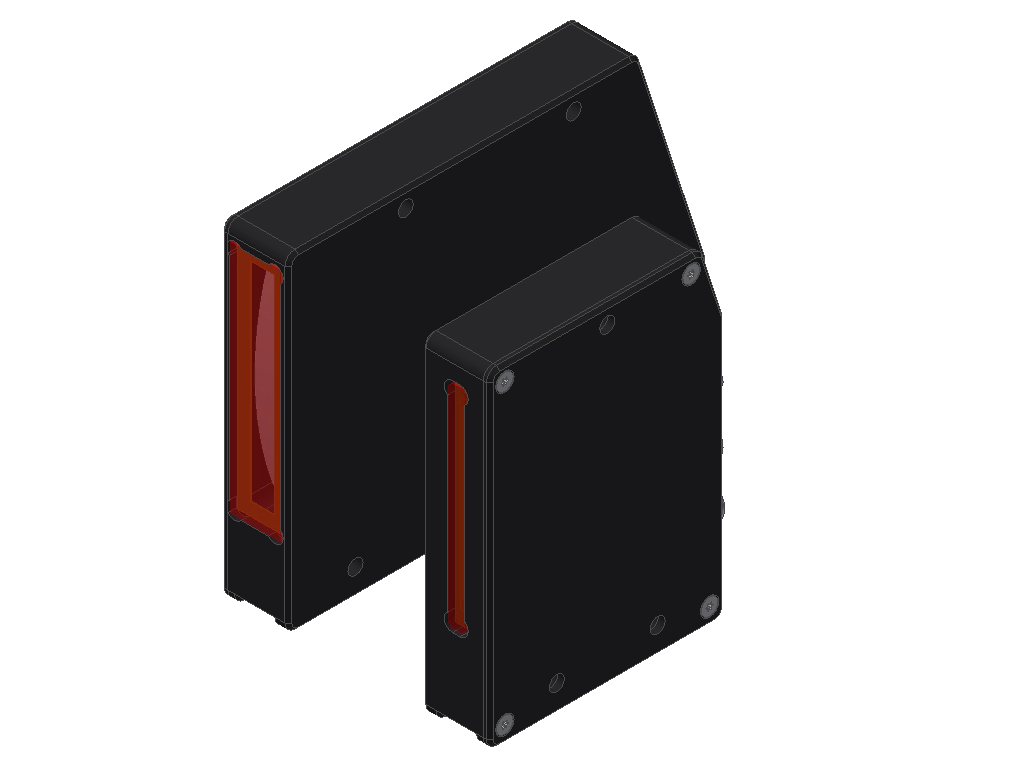
L-LAS-TB-50-T-AL-SC L-LAS-TB-50-R-AL-SC |
Line laser, 670nm, 0.39mW (CL. 1) | max. 2000mm | 48mm / 0.2% FSR (full scale range) | 64µm / ±64µm | 1 kHz | 2xIN, 3xOUT, 1xANA: 0...10V or 4...20mA | T:125x98x20 R:70x98x20 |
|
|
|
|
|
|
L-LAS-TB-75-T-AL-SC L-LAS-TB-75-R-AL-SC |
Line laser, 670nm, 0.39mW (CL. 1) | max. 2000mm | 73mm / 0.2% FSR (full scale range) | 64µm / ±64µm | 1 kHz | 2xIN, 3xOUT, 1xANA: 0...10V or 4...20mA | T:130x118x20 R:70x118x20 |
|
|
|
|
|
|
L-LAS-TB-100-T-AL-SC L-LAS-TB-100-R-AL-SC |
Line laser, 670nm, 0.39mW (CL. 1) | max. 2000mm | 98mm / 0.2% FSR (full scale range) | 64µm / ±64µm | 1 kHz | 2xIN, 3xOUT, 1xANA: 0...10V or 4...20mA | T:170x143x20 R:70x143x20 |
|
|
|
|
GENERAL TECHNICAL DATA:
| Software | Windows® PC software: L-LAS-Spray-Control-Scope |
| Design | 2-piece: Transmitter (-T-AL-SC) + receiver (-R-AL-SC) |
| Voltage supply | +24VDC (± 10%), reversed polarity protected, overload protected |
| Current consumption | <200mA |
| Max. switching current | 100mA, short-circuit proof |
| Light source | Semi-conductor laser, 670 nm, <0.39mW opt. power, DC-operation, Laser class 1 acc. to DIN EN 60825-1:2015-07 (IEC 60825-1:2014) |
| Line detector | depends on sensor type |
| Working distance | depends on sensor type |
| Measuring range | depends on sensor type |
| Resolution/reproducibility | depends on sensor type |
| Linearity | depends on sensor type |
| Optical filter | Interference filter |
| Analog output | Voltage 0...+10V or current 4...20mA |
| Digital outputs | OUT0 (BUSY): Activity indicator OUT1 (A): Measured value A within (green) or outside (red) of the tolerance limit OUT2 (B): Measured value B within (green) or outside (red) of the tolerance limit pnp bright-switching/npn dark-switching or pnp dark-switching/npn bright-switching Output polarity adjustable under Windows® on PC |
| Digital inputs | IN0: External trigger IN1: White balance Input voltage +Ub/0V, with protective circuit |
| Sensitivity | adjustable under Windows® on PC |
| Laser power correction | adjustable under Windows® on PC |
| LED display | LED red/green: OUT1 (A) LED red/green: OUT2 (B) LED yellow: BUSY LED yellow: POWER (multifunctional) |
| Scan frequency | depends on sensor type |
| Interface | RS232, parameterizable under Windows® |
| Housing dimensions | depends on sensor type |
| Housing material | Aluminum, anodized in black |
| Type of connector | Transmitter (-T-AL-SC): - to receiver: 4-pole fem. connecting Binder 712 Receiver (-R-CL-SC): - to PLC: 8-pole fem. connector Binder 712 - to PC: 4-pole fem. connector Binder 707 - to transmitter: 4-pole fem. connector Binder 712 |
| Connecting cables | Receiver (-R-AL-SC): - to PLC: cab-las8/SPS - to PC: cab-las4/PC, cab-4/USB or cab-4/ETH - to transmitter (-T-AL-SC): cab-las4-male |
| Operating temp. range | -10°C ... +50°C |
| Storage temp. range | -20°C ... +85°C |
| Enclosure rating | IP67 |
| EMC test acc. to | DIN EN 60947-5-2 |